Brilliant Tips About How Do I Create A Netlist

Unlocking the Secrets of Netlists
1. What Exactly Is a Netlist, Anyway?
Okay, let's start with the basics. Imagine you're building a Lego castle. You have all these individual bricks (resistors, capacitors, transistors — the usual suspects in electronics). A netlist is like the instruction manual telling you exactly how to connect those bricks together so your castle (circuit) actually stands up and does something useful, like, I don't know, defend against plastic dinosaurs.
In more technical terms, a netlist is a textual description of an electronic circuit. It specifies the components in the circuit and the connections between them, which we call "nets." Think of a "net" as a wire connecting two or more components. It's like the electrical roadmap, guiding the flow of signals through your design.
Why is it important? Well, almost every stage of electronic design relies on netlists. They're used for circuit simulation, PCB layout, and even manufacturing. So, understanding how to create one is a pretty valuable skill in the electronics world. Trust me, it's not as scary as it sounds (especially if you like Lego!).
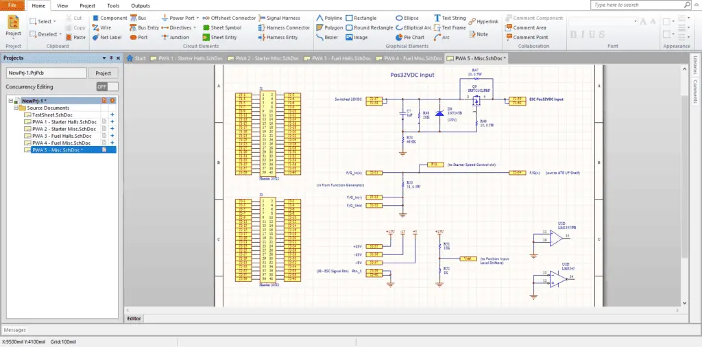
Essentially, the netlist bridges the gap between your schematic diagram (the visual representation of your circuit) and the physical realization of that circuit. It allows computers and software to understand the design and perform various tasks, from verifying its functionality to generating the instructions for building it. Think of it like the language that electronic design tools speak!
2. Different Flavors of Netlists
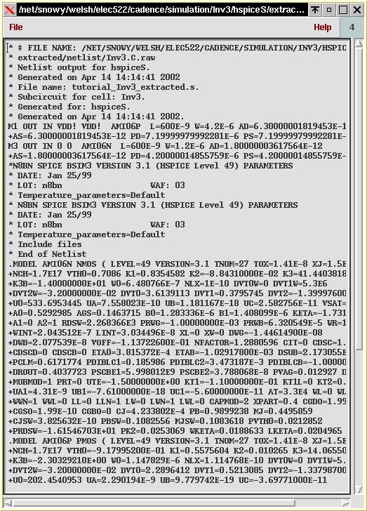
Just like ice cream comes in chocolate, vanilla, and strawberry, netlists come in different formats, each with its own quirks and advantages. Some common formats include Spice netlists (popular for circuit simulation), and formats used by specific PCB design software, like Allegro or Altium. The "flavor" you choose often depends on the tools you're using and what you want to do with the netlist.
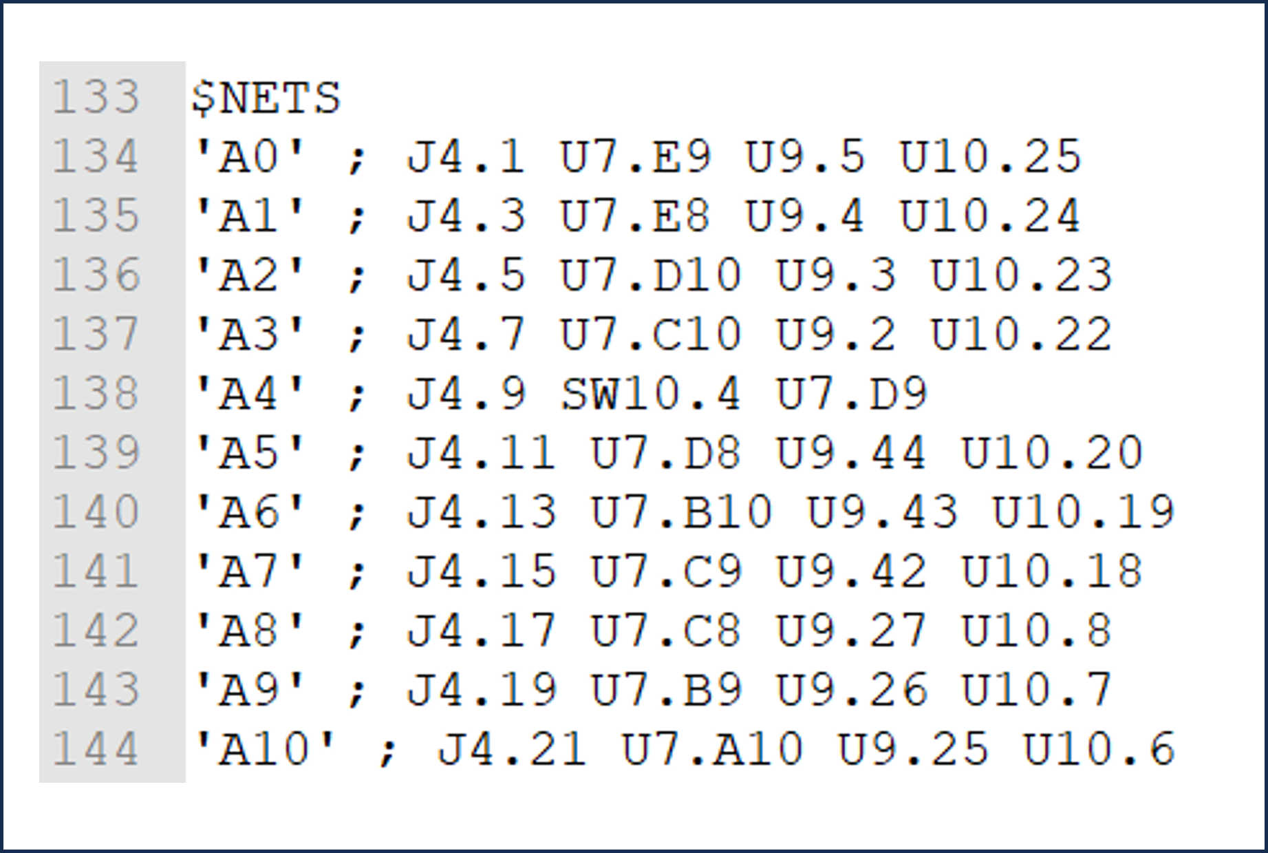
Spice netlists are relatively human-readable and focus on describing the electrical characteristics of the circuit. PCB netlists, on the other hand, contain more information about the physical layout, such as component footprints and pin locations. They need to guide the routing of traces on the printed circuit board.
Its important to pick the right format. Trying to use a Spice netlist for PCB layout would be like trying to use a banana as a hammer — technically possible, but probably not very effective. Each format is tailored for a specific purpose and workflow. So, before you start writing a netlist, figure out what software or tool you'll be using it with.
Also, many EDA (Electronic Design Automation) tools can automatically generate netlists from your schematic. So, learning the basics allows you to troubleshoot issues if the automatic generation has problems. It is helpful to understand what the generated netlist should look like!

Creating A Netlist
Getting Your Hands Dirty
3. Manual Netlist Creation
Okay, let's be honest: these days, most people don't create netlists entirely by hand. EDA software does a fantastic job of automating that process. But understanding the underlying structure of a netlist is still valuable. It can help you debug problems and understand what's going on "under the hood" of your design tools.
The basic structure of a netlist typically involves listing each component and then specifying which pins of that component are connected to which nets. Let's say you have a resistor (R1) connected between net "A" and net "B". The netlist entry might look something like this (in a simplified format):
R1 A B 1kThis line tells us that resistor R1 is connected between net A and net B, and its value is 1 kilohm. The specific syntax can vary depending on the netlist format. The core idea remains the same — defining components and their connections.
While creating a netlist manually, pay very close attention to detail! A single typo can introduce a short circuit or a disconnected component. Make sure component names are consistent with your schematic. Proofread your netlist carefully before using it. Think of it as writing code for your hardware. The computer will only do exactly what you tell it to do (even if it's wrong!).
4. A Simple Example
Let's look at another simplified example — an op-amp circuit. Imagine a basic inverting amplifier. You'll have an op-amp (OP1), two resistors (R1 and R2), and some connections to power supply rails (VCC and GND). A simplified netlist snippet might look like this:
OP1 OUT IN- VCC GND OPAMP_MODEL
R1 IN- IN 10k
R2 OUT IN 100k
VIN IN 1 SIN(0 1 1kHz)This is just a very simplified illustration. A real Spice netlist would be more detailed, including model parameters and simulation control statements.
In this case, we can see that the op-amp (OP1) has its output pin connected to "OUT," the inverting input connected to "IN-", the non-inverting input tied to "IN", and the power supply pins connected to "VCC" and "GND." Then we have two resistors, R1 and R2, connected to the appropriate nodes. Finally, a sine wave input source is connected to the node "IN".
Remember to refer to the component datasheets for pin names and numbers. The datasheet is your friend and an essential resource for getting those connections right. Also, use descriptive net names to improve readability and make your netlist easier to debug. Instead of just "NET1," use something like "OPAMP_OUTPUT."

How To Generate Netlist From Schematic Allegro System Capture YouTube
Let the Software Do the Heavy Lifting
5. The Magic of EDA Tools
Thank goodness for EDA (Electronic Design Automation) software! Instead of manually typing out netlists (which can be tedious and error-prone), these tools can automatically generate them from your schematic diagram. This dramatically speeds up the design process and reduces the risk of mistakes.
Most EDA tools, like KiCad, Eagle, Altium Designer, and OrCAD, have built-in netlist generation capabilities. The process usually involves first creating a schematic diagram of your circuit using the tool's graphical interface. Once the schematic is complete, you can then select a netlist format and generate the netlist with just a few clicks.
Before generating a netlist, make sure your schematic is clean and error-free. Check for unconnected pins, duplicate component names, and any other warnings or errors reported by the EDA tool. A "garbage in, garbage out" principle applies here. A flawed schematic will result in a flawed netlist, leading to problems down the road.
It's still important to understand the netlist generation settings in your EDA tool. You can usually customize various options, such as the netlist format, component naming conventions, and the inclusion of specific information. Knowing these settings allows you to tailor the netlist to the specific needs of your project.
6. Troubleshooting Netlist Generation
Even with automatic netlist generation, problems can sometimes arise. The most common issues include errors in the schematic, incompatible netlist formats, or incorrect component libraries. If you encounter a problem, the first step is to carefully review the error messages reported by the EDA tool.
Sometimes, the error messages can be cryptic and difficult to understand. In that case, try simplifying your schematic to isolate the problem. For example, you can temporarily remove sections of the circuit to see if the netlist generates successfully for the remaining portion.
Also, make sure that all the components in your schematic have valid footprints associated with them. The footprint defines the physical dimensions and pin locations of the component. Without a footprint, the EDA tool won't be able to include the component in the netlist correctly. If problems persist, consult the documentation for your EDA tool or search online forums for solutions. It's very likely someone else has encountered a similar issue!
Remember, even with automated tools, a basic understanding of netlist structure can significantly aid in troubleshooting and debugging. Don't be afraid to peek inside the generated netlist to see if the connections are as you intended. Knowledge is power!

How To Create Netlist YouTube
Validating Your Netlist
7. The Importance of Validation
So, you've created a netlist. Congratulations! But don't celebrate just yet. Before you hand it off to the PCB layout designer or load it into a circuit simulator, you need to validate it. This is a critical step to ensure that the netlist accurately represents your intended circuit design.
Validation involves checking the netlist for errors and inconsistencies. A simple visual inspection can catch some of the most obvious problems, such as missing components or incorrect connections. Compare the netlist to your schematic, paying close attention to component names and net names.
For more thorough validation, you can use a dedicated netlist checker tool. Many EDA tools have built-in netlist checkers that can automatically identify common errors, such as unconnected pins, short circuits, and duplicate component names. These tools can save you a lot of time and effort.
Beyond simply checking for errors, you should also verify that the netlist meets the requirements of the downstream tools that will be using it. For example, if you're using the netlist for PCB layout, make sure that it includes all the necessary information about component footprints and pin locations.
8. Simulation to the Rescue
One of the most effective ways to validate a netlist is through circuit simulation. Load the netlist into a circuit simulator like LTspice or PSpice and run some simulations to verify that the circuit behaves as expected. This allows you to catch design errors early in the process before they become expensive to fix.
When running simulations, focus on testing the critical aspects of your circuit. For example, if you're designing an amplifier, verify that it has the correct gain and bandwidth. If you're designing a filter, verify that it has the correct cutoff frequency and attenuation. If the simulations produce unexpected results, it's likely that there's an error in your netlist or your circuit design.
Also, carefully examine the simulation waveforms to identify any potential issues. Look for things like excessive noise, oscillations, or voltage clipping. These issues could indicate design flaws that need to be addressed before you proceed with the physical implementation of your circuit.
Validating your netlist may seem like a tedious task, but it's well worth the effort. By catching errors early, you can save time, money, and frustration in the long run. Think of it as an investment in the success of your project.

Everything You Need To Know About ScanWorks Interconnect Part 11
